clock
 clock copied to clipboard
Running a vintage secondary clock, using DCF77 or WWVB and Raspberry Pi Pico. Also a version that does not use Radio and uses a Pico W.


Clock
Reinvigorating/ recycling a handsome old clock and making it super-accurate, without any internet. Uses a Raspberry Pi Pico, a radio antenna and a couple of components to emulate a signal from a Mother clock. You can define the pulse interval as a parameter, so it works with a broad range of clocks (most take 60 seconds intervals, but some take 30 second or 1 second pulses).
European or US radio signals
The DCF77 signal is a radio signal that carries information from some Atomic Clocks. The signal covers most of Europe and is accurate to within a second over about 300,000 years (the DCF77 signal has been broadcasting the time since 1973 and in 2021 it was agreed to be continued for at least 10 more years).
The script also has code for WWVB, the signal used in the United States. To use WWVB, change the region parameter in main.py from DCF77 to WWVB. If you test it and it works, let me know.
(Japan uses JJY. Adding code for this is on the todo list)
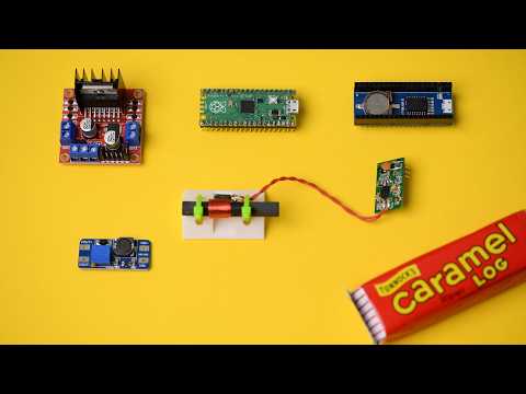
Hardware
- Old 'nebenuhr' clock with secondary mechanism (a mechanism that is controlled by pulses from the mother-clock)
- A ferrite receiver (for the DCF77 or WWVB signal)
- A microcontroller (Raspberry Pi Pico)
- Real time clock (RTC) (backup for any radio signal issues)
- H bridge (LN298), for the polarity switch that triggers the clock mechanism
- Step-up module to send correct voltage pulse to the clock (or a dc power supply, as used in the video)
Videos
An overview of how the clock works:

How the pieces are assembled:
Building your own clock
Assemble the Pico, step up transformer and H bridge. Note that the voltage of the step up tranformer may vary depending on the clock you're using.
Schematic
The antenna also needs 3.3V power and GND. They were omitted in order to keep the diagram tidy. If you're sending more than 12V (we used 24V) to the clock then make sure you remove the 5v jumper from the h-bridge.

Copy the files from this repository
  git clone https://github.com/veebch/clock
  cd clock
then send them your Pico using ampy
sudo ampy -p /dev/ttyACM0 put ./*
Edit the file firstruntime.txt to show the time that the clock is showing before the first run. This should be the only time you need to do this, the code will keep track of time after power-off.
Running
The code in main.py executes as soon as the pico is powered on, but if you run while connected to Thonny then you will see the terminal output showing the signal as it is decoded. If the bars look irregular or have gaps in, then there is an issue with the dcf77 signal. A clear signal will look something like this:

Code used
The DCF77 part of the code was based on demogorgi/set-rtc-using-dcf77-via-dcf1.
Licence
GPL 3.0