pico-sdk
 pico-sdk copied to clipboard
Adding 10-bit i2c addressing support to the SDK
Fixes #720
Raspberry Pi Pico SDK with 10-bit i2c addressing support
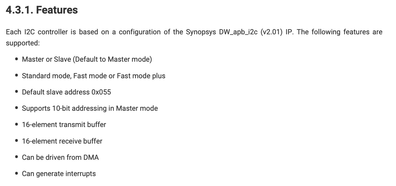
As of v1.3.0 of the SDK, neither 10-bit i2c master mode nor 10-bit i2c slave mode is implemented.
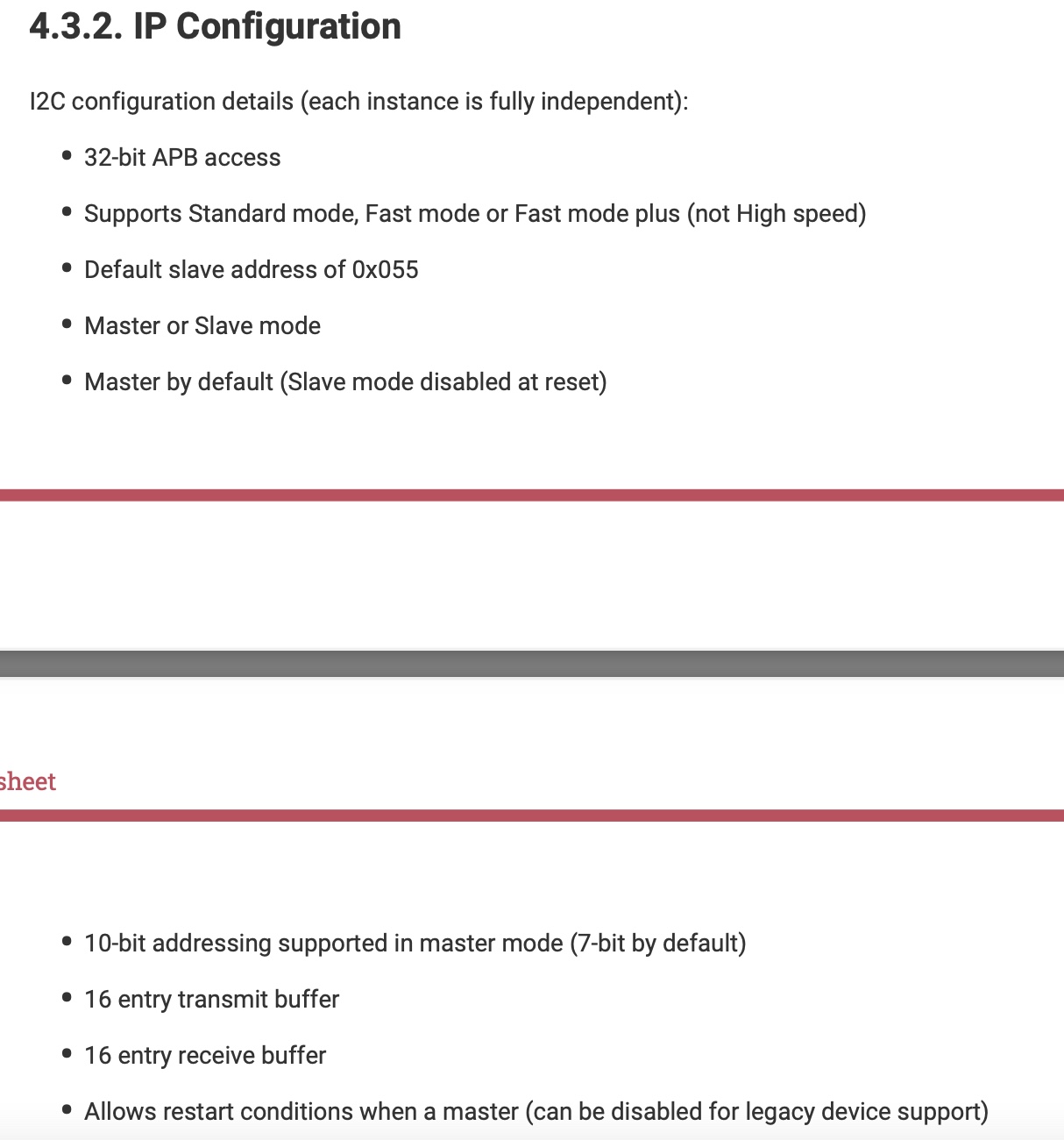
The RP2040 Datasheet suggests, in two places that I can find, that 10-bit i2c addressing is not supported in slave mode.
 |
|---|
| Figure 1 - Suggesting 10-bit addressing is only available in Master mode |
 |
|---|
| Figure 2 - Also suggesting 10-bit addressing is only available in Master mode |
Introducing 10-bit i2c addressing support
In the revised i2c.h there are 10 new functions
- i2c_init_10bit
- i2c_set_slave_mode_10bit
- i2c_write_blocking_until_10bit
- i2c_read_blocking_until_10bit
- i2c_write_timeout_us_10bit
- i2c_write_timeout_per_char_us_10bit
- i2c_read_timeout_us_10bit
- i2c_read_timeout_per_char_us_10bit
- i2c_write_blocking_10bit
- i2c_read_blocking_10bit
In the revised i2c.c there are 3 new functions
- i2c_reserved_addr_10bit
- i2c_write_blocking_internal_10bit
- i2c_read_blocking_internal_10bit
All prototypes are identical to their non-10-bit-qualified counterparts, except wherever there is a uint8_t addr parameter, it has been replaced with uint16_t addr.
Their functionality is also identical, but adapted to 10-bit addressing.
Example usage is found at RP2040_10bit_i2c_host.c and RP2040_10bit_i2c_periph.c
Overview of a 10-bit i2c transaction using the examples
RP2040_10bit_i2c_host and RP2040_10bit_i2c_periph were built using the modified SDK proposed here.
Due to the limitations of the scope used to measure the i2c bus, the transaction will be split across 6 different pictures.
In whole, the i2c host writes 2 bytes to the bus for address 0x02CF, then asks the device with address 0x02CF for 3 bytes in response.
 |
|---|
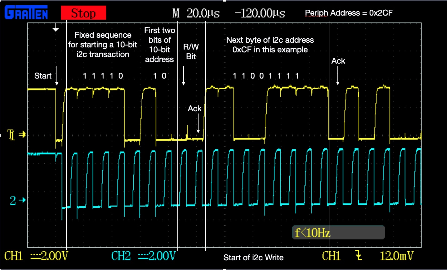
| Figure 3 - Start of the i2c host write |
The host initiates a transaction by dropping SDA while SCL is held high.
The next 5 bits are a specific sequence, 0b11110, reserved by the i2c spec to signal a 10-bit transaction, followed by the 2 most significant bits of the 10-bit address, in this case 0x2.
The next byte delivers the rest of the 10-bit address, 0xCF.
 |
|---|
| Figure 4 - End of the i2c host write |
Here, the 2 bytes are written to the bus, 0xA5 proceeded by 0x5A with the required ACK inbetween.
 |
|---|
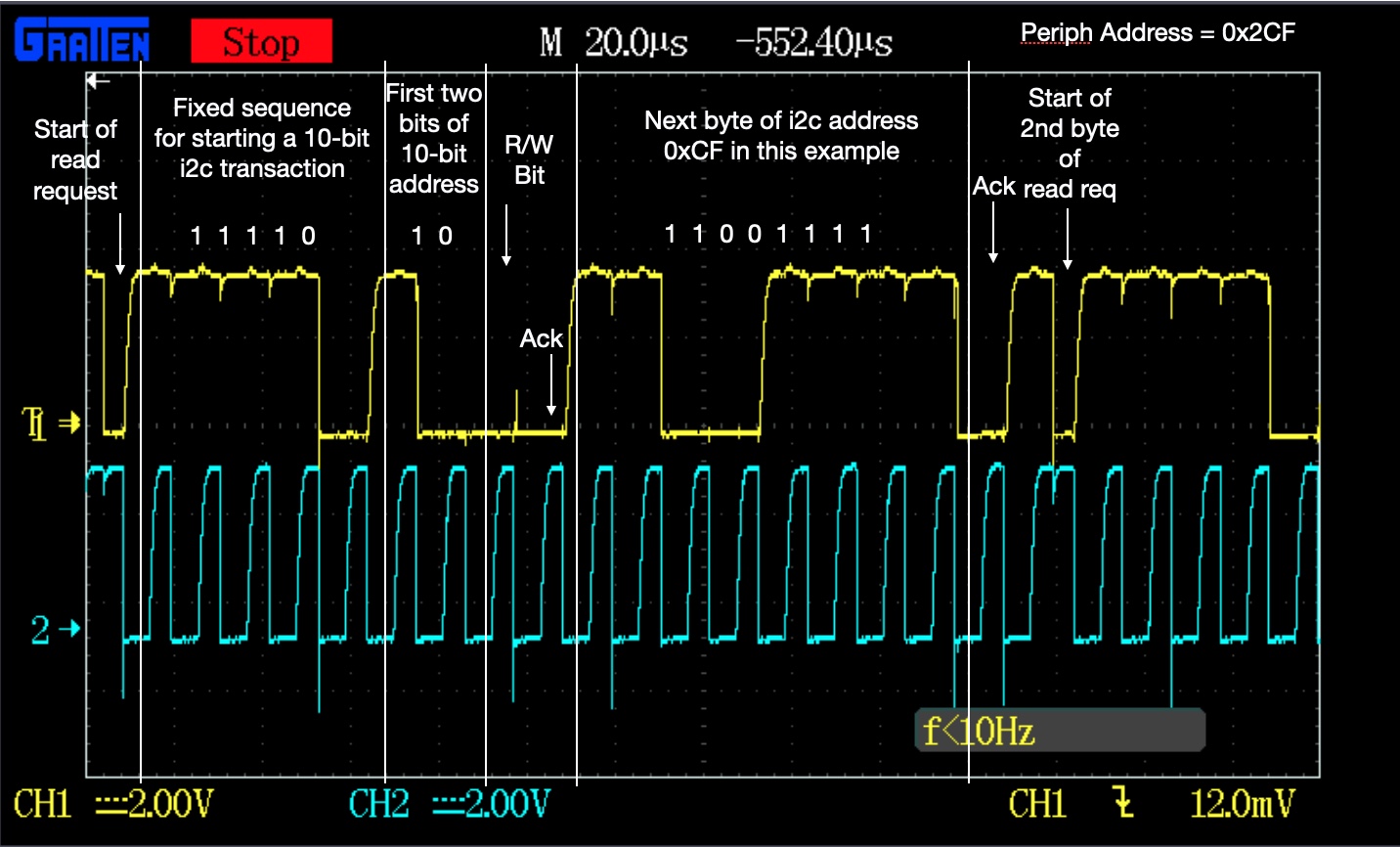
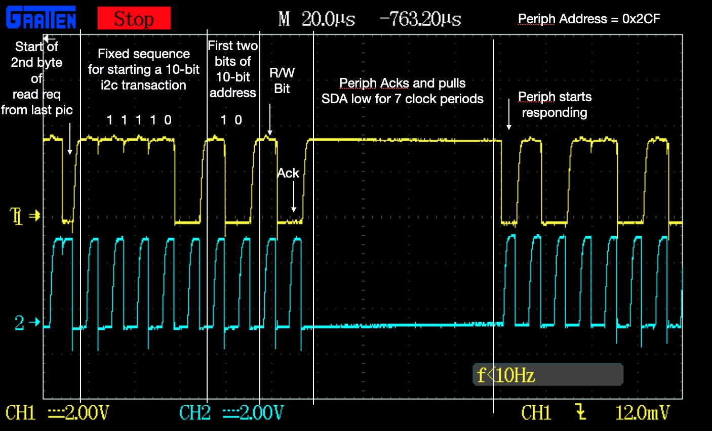
| Figure 5 - Start of the i2c host read request |
The host then starts a read request by transmitting the peripheral address, 0x02CF in a similar manner to Figure 3. The R/W bit suggests a write, even though this is a read request. This is solved by transmitting a 3rd byte with the Read bit set.
 |
|---|
| Figure 6 - Start of the i2c host read request |
The host transmits its 3rd and final byte for the read request, this is a repeat of the first start byte, with the reserved 0b11110 and 2 most significant bits of the periph address, but with the Read bit set.
The peripheral then holds SDA low while it prepares to transmit its data.
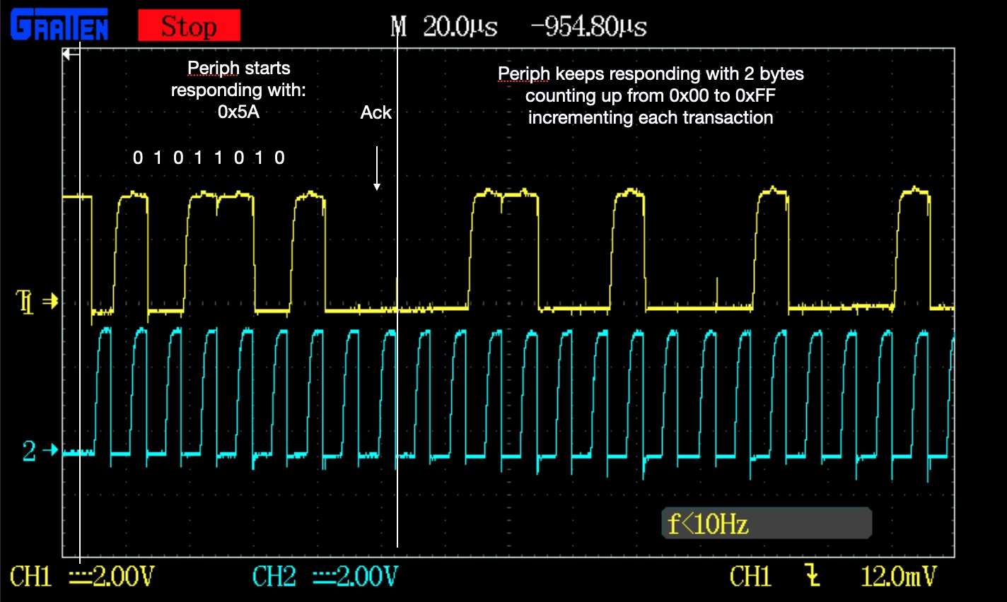 |
|---|
| Figure 7 - Start of the i2c periph write |
The periph transmits its data and gets the required ACK, it transmits 3 bytes in total. The first being a constant 0x5A, and the last two bytes are a counter that is incremented each time a i2c transaction takes place.
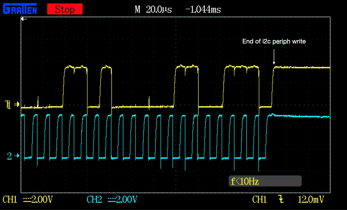 |
|---|
| Figure 8 - End of the i2c transaction |
At the end, the host has acknowledged the bytes its expects and stops driving SCL.
In conclusion
The RP2040 does, in fact, support 10-bit addressing in both host and peripheral modes. The changes required to the SDK to fully support 10-bit addressing are provided in i2c.h and i2c.c