raspberry-pi-pcie-devices
 raspberry-pi-pcie-devices copied to clipboard
Test Radxa CM3 on CM4 Boards
I have a Radxa CM3, which has a RockChip RK3566. I want to test it with some things, for science. This issue will be a compendium of all my knowledge.

Relevant links:
- https://wiki.radxa.com/Rock3/CM3
- https://forum.radxa.com/t/introduce-radxa-cm3-a-drop-in-replacement-for-the-cm4/
First up, getting the thing to boot (either to eMMC flashing mode, or to boot normally) is... interesting.
Booting with CM4 IO Board
It looks like if you just supply power (e.g. plug in the board), it won't boot by itself. The process for boot seems to be:
- Plug in power
- Put a jumper on pins 13-14 on the 14-pin header (GLOBAL_EN).
Getting into eMMC mass storage mode with CM4 IO Board
Similarly, to flash the built-in eMMC through mass storage / OTG mode, I have to perform a little bit of a dance:
- Plug in power
- While depressing the little gold button between the SoC and WiFi chip...
- Put a jumper on pins 13-14 on the 14-pin header (GLOBAL_EN).
At this point, if I run lsusb I can see a new device appear:
Bus 002 Device 004: ID 2207:350a Fuzhou Rockchip Electronics Co., Ltd. Composite Device
Flashing a new OS to the CM3
(Following this guide).
-
Download an image from the rock-3-images-released repo.
-
Follow steps above for getting board into mass storage mode.
-
Install necessary utilities:
brew install automake autoconf libusb lsusb -
Set up
rkdeveloptool:git clone https://github.com/rockchip-linux/rkdeveloptoolcd rkdeveloptoolautoreconf -i./configuremakesudo cp rkdeveloptool /usr/local/bin/(this step is optional... can run it locally if you want)
-
Run
rkdeveloptool ldto make sure you see the device (should showDevNo=1 Vid=0x2207,Pid=0x350a,LocationID=202 Maskrom) -
Download the relevant .bin file from this page - I used this one.
-
Download the .bin to the board:
rkdeveloptool db rk356x_spl_loader_ddr1056_v1.06.110.bin(should complete in a couple seconds, then showDownloading bootloader succeeded.) -
Write the image from step one to the board:
rkdeveloptool wl 0 ~/Downloads/[image]-gpt.img -
Reboot the device:
rkdeveloptool rd
Note: If you need to wipe the eMMC first (I did the first time I got my early test board), download this zero.img and write it to the board.
Right now, no matter what I do, this thing boots to this desktop after I see a 'RockChip kernel' splash screen for a couple seconds:
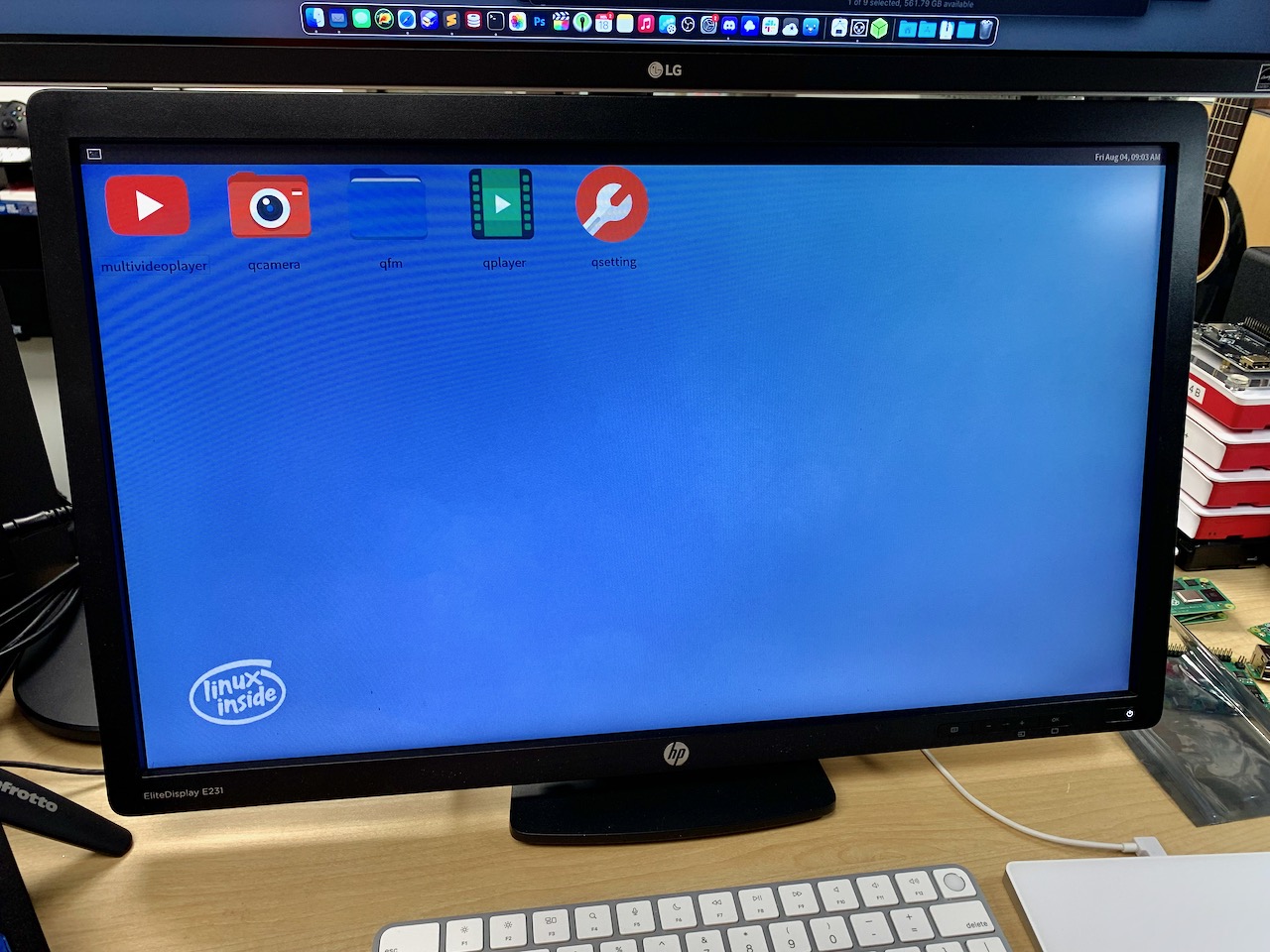
@robtech21 - No clue, this was an earlier board that someone else was testing with, so it seems to be something kinda custom they were working on. I can't get USB to work and can't log in over the network, so I'm just trying to figure out how to re-flash the whole thing so it doesn't boot to this.
with the lack of USB I summize there is debug output somewhere
the desktop looks like android with a menu bar, maybe try with a touch screen?
with the lack of USB I summize there is debug output somewhere
the desktop looks like android with a menu bar, maybe try with a touch screen?
The UI kinda reminds me of an XFCE interface, but maybe that's just me going slowly insane after using it for a long time. Radxa does offer Debian, Ubuntu, and Android iirc
FYI I'm also beginning to test the SOQuartz: https://github.com/geerlingguy/raspberry-pi-pcie-devices/issues/336
Testing this with a new set of instructions from Discord:
- Plug in 12V barrel plug power.
- Hold down the button next to the WiFi shield AND the button next to the SPI flash chip.
- Place jumper across 13/14 (GLOBAL_EN) on CM4 IO Board.
- Release buttons
- Run
rkdeveloptool ld(should getDevNo=1 Vid=0x2207,Pid=0x350a,LocationID=202 Maskrom). - Run
rkdeveloptool db rk356x_spl_loader_ddr1056_v1.06.110.bin(should getDownloading bootloader succeeded.)
That seems to have worked. Now when I boot not in bootloader flashing mode, I see blinking green ACT LED.
Still nothing—it is still booting to that Qt looking custom desktop, and USB still doesn't work.
I tried attaching to UART through a USB-to-Serial adapter, and tried testing baud rates of 1500000, 115200, and 9600, but I just get gibberish no matter what (but there is gibberish output during boot as if it's outputting something... just not sure what baud):

@ProKn1fe - I'll be covering that more later, for now go to the links in the original comment and it has all the specs. I am just trying to get the thing in a bootable state for now, before I can work on any kind of comparisons.
Checking my USB-UART adapter, maybe it can't handle the high 1500000 baud rate...
$ lsusb
Bus 002 Device 023: ID 10c4:ea60 Silicon Laboratories, Inc. CP2102 USB to UART Bridge Controller  Serial: 0001
From the Radxa wiki on serial console access:
The default baudrate of ROCK 3 is 1500000(1.5Mbps), please check if your USB to TTL cable support 1.5Mbps baudrate. Some model of CP210X and PL2303x have baudrate limitation,and the FT232RL have some power issue(20211112), please check the specified model. We also tested that some cable does not work well. Make sure choose a high quality one. The instructions below use a CH340_series based cable.
I just ordered a set of 5 CH340-based adapters, hopefully they'll work better.
Ah, just realized I also have a spare USB-UART adapter that Broadcom sent when they sent a MegaRAID card for testing:
Bus 002 Device 024: ID 0403:6001 Future Technology Devices International Limited FT232R USB UART Serial: AR0JTLV4
Unfortunately, it doesn't seem like that adapter worked either. I tried screen /dev/tty.usbserial-AR0JTLV4 1500000 and got no output (though it would drop a question mark on each boot).
Here's the setup:

(Tested with both SOQuartz and Radxa. Also validated that everything worked at 115200 baud with a Pi, so I guess the old chip doesn't work with 1.5 Mbps serial data either.)
On macOS, if you want to get serial output at 150000, which is not a standard baud rate for macOS, the working usb to ttl chip is prolific series(they provide universal driver for m1&intel), the working serial tool we tested is Coolterm(universal app).
https://wiki.radxa.com/Rock3/dev/serial-console#macOS
FT232R should also support 150000, but screen doesn't. Check coolterm.
@hipboi - Thanks, didn't realize screen wouldn't support it, at least not the version that ships with macOS. I'll try CoolTerm soon and report back what happens.
No clue how, but suddenly after booting it up again today, I can get the keyboard and mouse working! Things are looking much more positive after fighting with the board last week.
[root@RK356X:~]# uname -a
Linux RK356X 4.19.172-01402-g0ae0afc2911a-dirty #2 SMP Tue Aug 31 10:53:05 CST 2021 aarch64 GNU/Linux

[root@RK356X:~]# cat /etc/os-release
NAME=Buildroot
VERSION=2018.02-rc3-g5bc4d3de1e-dirty
ID=buildroot
VERSION_ID=2018.02-rc3
PRETTY_NAME="Buildroot 2018.02-rc3"

[root@RK356X:~]# cat /etc/issue
Welcome to RK356X Buildroot
Also interesting, in dmesg:
[ 0.000000] Machine model: rockchip,rk3568
Not sure why the Debian image I'm flashing isn't booting still. Maybe the image itself isn't actually Debian but is, indeed, buildroot??
[root@RK356X:~]# df -h
Filesystem      Size  Used Avail Use% Mounted on
/dev/root       5.9G  467M  5.2G   9% /
devtmpfs        913M     0  913M   0% /dev
tmpfs           922M     0  922M   0% /dev/shm
tmpfs           922M  368K  921M   1% /tmp
tmpfs           922M  220K  921M   1% /run
/dev/mmcblk0p7  126M   13M  110M  10% /oem
/dev/mmcblk0p8  1.1G  452K  1.1G   1% /userdata
I also just wrote ubuntu focal to the eMMC using the same method (rkdeveloptool wl 0 rockcm3_ubuntu_focal_server_arm64_20210914_0552-gpt.img), and after rebooting, it still boots into the Rockchip Kernel buildroot OS. No clue how to bypass that.
@geerlingguy This is because the rkdeveloptool write the image to SPI flash, which is absolutely wrong but no error reported. We feedback this to Rockchip to fix it. At the meanwhile, if you want to write to eMMC, you will have to disable the SPI flash by press and hold the button besides it.
@hipboi - I did that too; I held both the SPI flash button and the button next to the WiFi chip, and then booted it (and it showed up on my Mac so I could flash it with rkdeveloptool, and then wrote the image (tried with both Debian and Ubuntu), and it's still always booting into the rockchip buildroot kernel environment. Image for reference:

Do I need to use a different utility besides rkdeveloptool when writing to the eMMC? I can record a video of the exact process if you'd like, too. I've flashed it at least five times now holding down both buttons, and a few times prior to that only holding down the button I label 'recovery / loader'.
I just installed CoolTerm (brew install --cask coolterm), and will test it out later, too.
Good news! Even my cheap CP2102 adapter sees to be able to handle 1.5 Mbps using CoolTerm — so I can finally get UART.
All right, so copying all the data from right after issuing reboot now to when the kernel started booting up: https://gist.github.com/geerlingguy/fafd85e7984b0a67f444778a6f620af4
Could this be the issue?
U-Boot SPL board init
U-Boot SPL 2017.09-ga1f6fc00a0-210413 #ldq (Apr 13 2021 - 11:35:00)
unknown raw ID phN
unrecognized JEDEC id bytes: 00, 00, 00
Trying to boot from MMC2
MMC error: The cmd index is 1, ret is -110
Card did not respond to voltage select!
mmc_init: -95, time 10
spl: mmc init failed with error: -95
Trying to boot from MMC1
SPL: A/B-slot: _a, successful: 0, tries-remain: 7
## Verified-boot: 0
## Checking atf-1 0x00040000 ... sha256+ OK
## Checking uboot 0x00a00000 ... sha256+ OK
## Checking fdt 0x00b221f0 ... sha256+ OK
## Checking atf-2 0xfdcc9000 ... sha256+ OK
## Checking atf-3 0xfdcd0000 ... sha256+ OK
## Checking optee 0x08400000 ... sha256+ OK
Jumping to U-Boot(0x00a00000) via ARM Trusted Firmware(0x00040000)
Total: 220.547 ms
This is with no microSD card inserted in the official IO Board.
Also, I plugged in a SATA PCIe card, and it initially gets identified in the Rockchip kernel, but boot stalls out after a while with:
[   61.540550] rcu: INFO: rcu_sched detected stalls on CPUs/tasks:
[   61.540569] rcu: .2-...0: (1 GPs behind) idle=522/1/0x4000000000000000 softirq=60/61 fqs=5964
[   61.540574] rcu: .(detected by 1, t=18002 jiffies, g=-1055, q=108)
[   61.540582] Task dump for CPU 2:
[   61.540587] rk-pcie         R  running task        0    54      2 0x0000002a
[   61.540596] Call trace:
[   61.540609]  __switch_to+0xc0/0x124
[   61.540616]  0x3
First, I am sorry for the confusion, the sample is a very early engineering sample, to write image to eMMC, you should do:
- Hold both buttons to go to maskrom mode,
rkdeveloptool ldshould see maskrom - Now hold only the SPI flash button, and run
rkdeveloptool db rk356x_spl_loader_ddr1056_v1.06.110.bin, so that rkdeveloptool will not detect the SPI flash - After step 2, you can release SPI button now since the loader is running and it thinks there is no spi flash, now you can write to emmc with
rkdeveloptool wl 0 xxx.img
For future release, we will not put both SPI flash and eMMC at the same time, also, use a switch instead of a button for the boot mode select.
Btw, we've fixed the picocom on M1. You can install from source with:
brew install --build-from-source radxa/picocom/picocom
@hipboi - ah, I wasn't holding the SPI button during the db command. I'll try that and report back!
Has anyone found device tree .dts files for this board? There are multiple parts to the device tree.
- The CM3 module itself.
- The motherboard the CM3 is plugged into. (this be will vary if one uses different boards with the module)
- Optional device tree overlays - so one can switch features on/off
Once one has the correct device tree files, I would expect it to work ok with almost any arm64 linux kernel. If you are playing with .dtb files, you are fighting a loosing battle.
dtsi for the cm3 module itself: https://github.com/radxa/kernel/blob/stable-4.19-rock3/arch/arm64/boot/dts/rockchip/rk3566-radxa-rock-3-compute-module.dtsi
dts for using on rpi cm4 io board: https://github.com/radxa/kernel/blob/stable-4.19-rock3/arch/arm64/boot/dts/rockchip/rk3566-radxa-cm3-rpi-cm4-io.dts
dts for using on radxa cm3 io board: https://github.com/radxa/kernel/blob/stable-4.19-rock3/arch/arm64/boot/dts/rockchip/rk3566-radxa-cm3-io.dts