SKR-2
 SKR-2 copied to clipboard
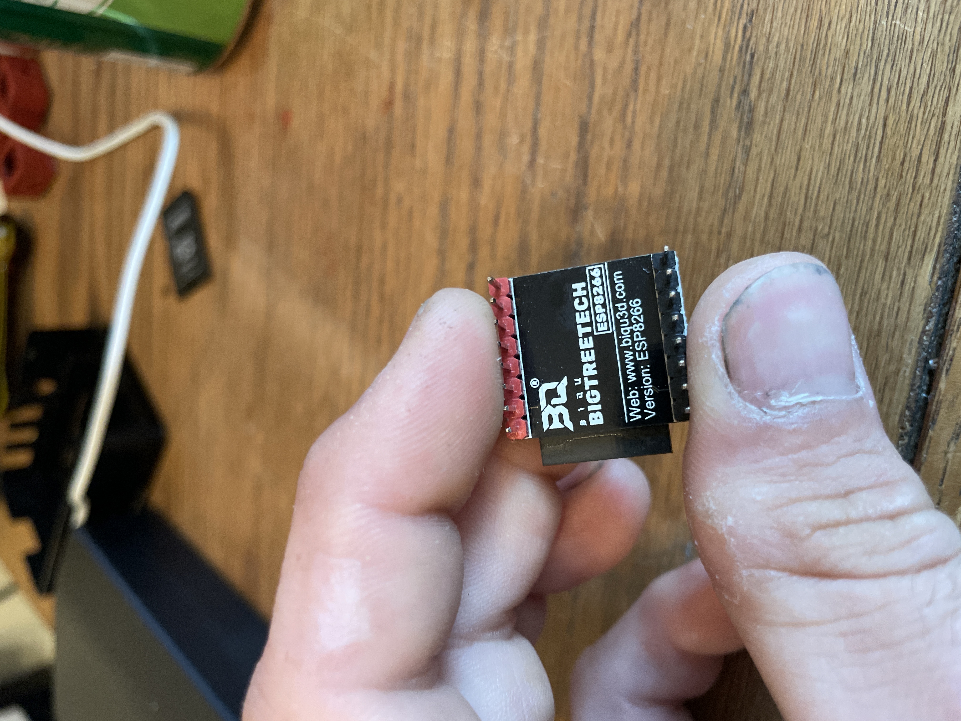
Matching Wifi module
Is the header for the Wifi module compatible with the MKS Robin-WIFI module (ESP-12S)? Will there be a version with external antenna? (ESP-07S)
Those MKS wifi modules physically fit, but BTT-specific wifi module firmware wasn't available before the V2 was publicly announced, so I can't confirm if they work.

Will there be a version with external antenna? (ESP-07S)
That's the plan.
Thanks a lot! If it is physically matching, it should work, because the pins are broken out one to one. flashing another firmware is not a big deal.
Are the WiFi modules available for purchase? I have searched and can't find them in the format pictured.
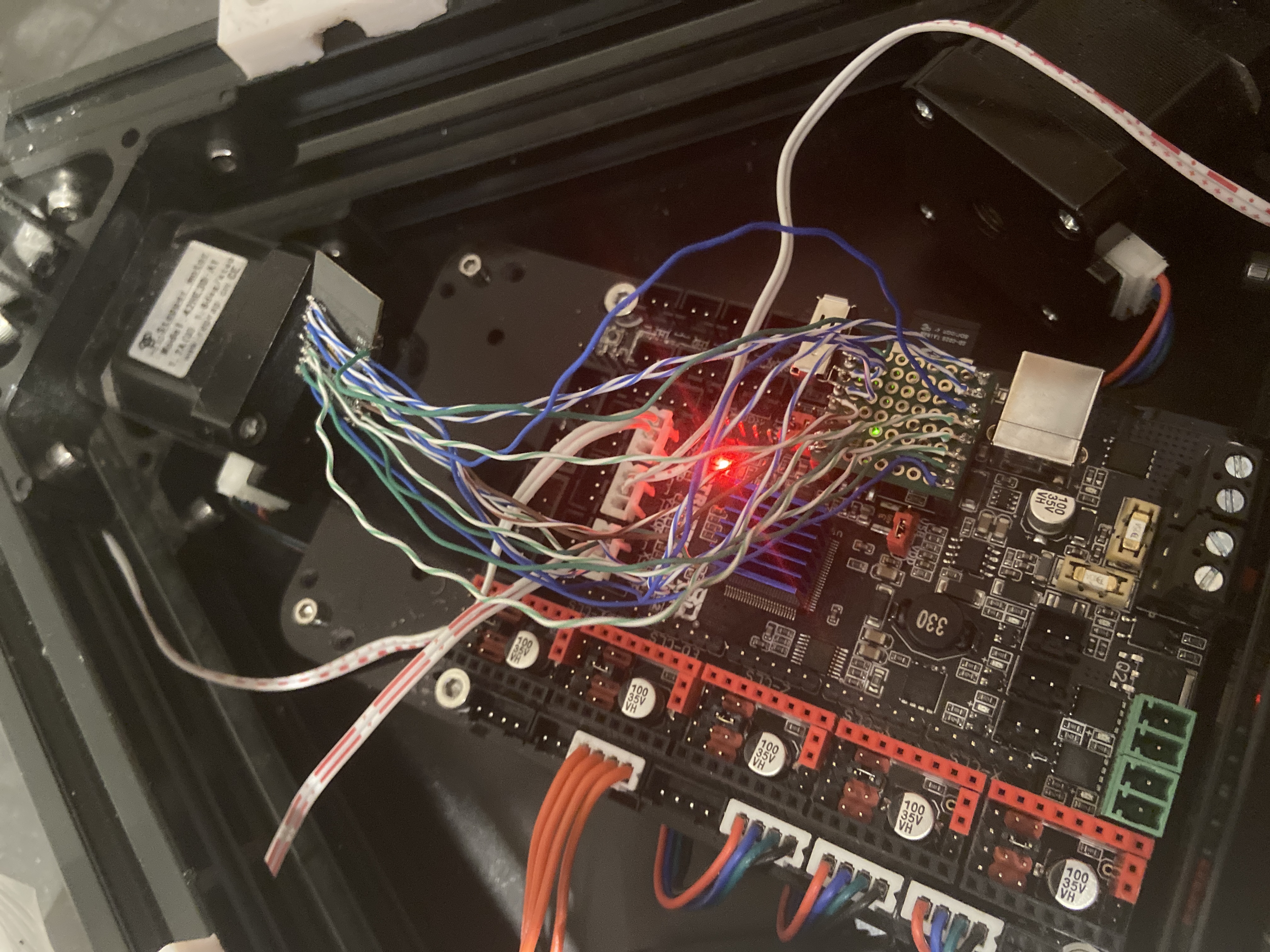
Looks like I will have do some soldering and make a DuPont wire spider then 🤔
The module I wrote about is aviable but not from BTT.. just google "MKS Robin-WIFI module". It is not clear if it is working right out of the box, or we have to use a custom firmware by BTT. However, I don´t see a reason why it should not work - physically.
Glad I found this, been trying to figure this out myself the last day. Good to know BTT is going to release a solution to this, however wish they would’ve done so prior to announcing the board. Can’t wait to get this baby in my hands!
They got the WIFI module up for sale. But it seems like its the same as the Makerbase version? At least I hope the MKS also works because i bought one because of it.
https://www.aliexpress.com/item/1005002548703795.html?spm=2114.12010611.8148356.7.384e39774iqQrq
They got the WIFI module up for sale. But it seems like its the same as the Makerbase version?
At least I hope the MKS also works because i bought one because of it.
https://www.aliexpress.com/item/1005002548703795.html?spm=2114.12010611.8148356.7.384e39774iqQrq
They both utilize the same ESP-12S WiFi module, but it's possible the circuits within the board their soldered to could vary. Only way to know 100% is to cross reference the pinout of both breakout boards.
Going to do some research and see what I can find, thanks for sharing I've been checking every few days for this to appear. Hopefully I can find it on Amazon, STILL waiting for my SKR 2 to make it into the states despite being ordered 2 1/2 weeks ago.
Doing a HUGE overhaul to my Ender 3 as well as building an enclosure for it.
They got the WIFI module up for sale. But it seems like its the same as the Makerbase version? At least I hope the MKS also works because i bought one because of it. https://www.aliexpress.com/item/1005002548703795.html?spm=2114.12010611.8148356.7.384e39774iqQrq
They both utilize the same ESP-12S WiFi module, but it's possible the circuits within the board their soldered to could vary. Only way to know 100% is to cross reference the pinout of both breakout boards.
Going to do some research and see what I can find, thanks for sharing I've been checking every few days for this to appear. Hopefully I can find it on Amazon, STILL waiting for my SKR 2 to make it into the states despite being ordered 2 1/2 weeks ago.
Doing a HUGE overhaul to my Ender 3 as well as building an enclosure for it.
It looks like the boards have the same pinout but there is a resistor/capacitor on the back of the board and the BTT dosnt have that.
Same here, building a heated enclosure for the Ender-3 xD
It looks like the boards have the same pinout but there is a resistor/capacitor on the back of the board and the BTT dosnt have that.
Same here, building a heated enclosure for the Ender-3 xD
Hmm may be worth exploring, did you find the diagram for the other board? I haven't made it to the computer yet to look.
I'm not going to heat mine at least not at first. From what I've seen/read, being inside an enclosure and the protection from sudden drafts and/or temperature changes is enough to mitigate most issues with things like ABS, Polycarbonate, Nylon, etc. The ambient air will naturally heat from heat dissipated from the bed, hotend, and steppers. I'm also rewiring everything to remove the power supply and control board outside the enclosure as well and upgrading to a mains powered bed.
Oh and also completing my linear rail conversion, no more v-slot rollers! 😍
Hi, i tried to solder an esp-12S to an adapter board to see if it works and unfortunately it doesnt work :(

The esp-12S module came from a btt rrf wifi board that costed me over 20€ :/

Grab yourself one of these! Their cheap as hell and while I haven’t hooked mine up yet, I’d venture to guess it work just fine and if nothing else will be way cleaner than all those wires! 😂

unfortunately this is not an option in Italy because nobody sells that module. the only way to get it is to order it from china, but shipping would take a long time. I think I have to throw this skr2 and buy the 1.4 instead
I am in the USA and ordered mine on eBay, which came from China(direct from BTT) and yes did take a little bit. But being in Italy, geographically your a hell of a lot closer than I am and in theory should reach you quicker. Besides going to take just as long for the SKR 1.4 to arrive to you. Just my two thoughts. Then again I bought the module intending to use it on the SKR 2 once I finally received my replacement board. Now I have the new Octopus V1.0 and the PiTFT I’m attempting to setup and install so I won’t even use the module until I build a new printer. 🤷♂️
On Thu, Jul 1, 2021 at 17:33 cparu @.***> wrote:
unfortunately this is not an option in Italy because nobody sells that module. the only way to get it is to order it from china, but shipping would take a long time. I think I have to throw this skr2 and buy the 1.4 instead
— You are receiving this because you commented. Reply to this email directly, view it on GitHub https://github.com/bigtreetech/SKR-2/issues/3#issuecomment-872631704, or unsubscribe https://github.com/notifications/unsubscribe-auth/APXQEBZUNR6QOQWUKRGIS3TTVUCOVANCNFSM42NHQJTA .
-- Matthew Glass 503-810-7980
I measured the pinout of the BTT ESP-12S module.. they are one to one - no pins are flipped. So if you soldered everything the right way, it should be fine. However, I don´t tested the module and do not have any hints on firmware etc..
I measured the pinout of the BTT ESP-12S module.. they are one to one - no pins are flipped. So if you soldered everything the right way, it should be fine. However, I don´t tested the module and do not have any hints on firmware etc..
I am pretty sure i soldered everything correctly, even if the esp12S is very small and maybe i have damaged it while removing from the BTT RRF bord. But i think it is working fine because when the SKR boots up, the blue led on the esp blinks but then it doesnt do anything. I think is something related to software, i would like to know if somebody has else tried to solder a non-BTT esp to the skd and if it worked for him or not.
We have users on the teamgloomy discord using home made adapters without issue
On Sun, Jul 4, 2021, 1:42 AM cparu @.***> wrote:
I measured the pinout of the BTT ESP-12S module.. they are one to one - no pins are flipped. So if you soldered everything the right way, it should be fine. However, I don´t tested the module and do not have any hints on firmware etc..
I am pretty sure i soldered everything correctly, even if the esp12S is very small and maybe i have damaged it while removing from the BTT RRF bord. But i think it is working fine because when the SKR boots up, the blue led on the esp blinks but then it doesnt do anything. I think is something related to software, i would like to know if somebody has else tried to solder a non-BTT esp to the skd and if it worked for him or not.
— You are receiving this because you are subscribed to this thread. Reply to this email directly, view it on GitHub https://github.com/bigtreetech/SKR-2/issues/3#issuecomment-873492068, or unsubscribe https://github.com/notifications/unsubscribe-auth/AATUSBX3FNEDUSMULT3HGWTTV6U6DANCNFSM42NHQJTA .
Are you guys running Marlin? If so, what Serial port definitions are you using? I've already programmed my BTT ESP-12S(8266), but I'm not sure if my compile is correct;
// Choose the name from boards.h that matches your setup
#ifndef MOTHERBOARD
  #define MOTHERBOARD BOARD_BTT_SKR_V2_0_REV_B
#endif

/**
 * Select the serial port on the board to use for communication with the host.
 * This allows the connection of wireless adapters (for instance) to non-default port pins.
 * Serial port -1 is the USB emulated serial port, if available.
 * Note: The first serial port (-1 or 0) will always be used by the Arduino bootloader.
 *
 * :[-1, 0, 1, 2, 3, 4, 5, 6, 7]
 */
#define SERIAL_PORT -1 //

/**
 * Serial Port Baud Rate
 * This is the default communication speed for all serial ports.
 * Set the baud rate defaults for additional serial ports below.
 *
 * 250000 works in most cases, but you might try a lower speed if
 * you commonly experience drop-outs during host printing.
 * You may try up to 1000000 to speed up SD file transfer.
 *
 * :[2400, 9600, 19200, 38400, 57600, 115200, 250000, 500000, 1000000]
 */
#define BAUDRATE 115200
//#define BAUD_RATE_GCODE     // Enable G-code M575 to set the baud rate
If I keep "SERIAL_PORT -1" I get a successful compile, but I'm not sure if it will actually recognize the ESP Wi-Fi module though
perdonen, entonces el modulo de mks wifi funciona en la btt skr2 ? yo solo necesito la comunicación con cura sin esp3d, esto seria posible?