CuraEngine
 CuraEngine copied to clipboard
Feature Request: Radial Infill
This is an issue originally mentioned in the cura github page, but I think it belongs here.
I wanted to print a sort of pythagoras cup in which the external radius was determined by the size of the mount it was supposed to fit and the internal radius was determined by the volume it was supposed to hold. Therefore, the walls ended being somewhat thick on a big part, requiring a lot of infill. I only needed it to be stiff on the radial axis in order to maintain its volume, so I was very disappointed when I couldn't find any infill pattern that efficiently matched my load case. Take a look at this layer view:
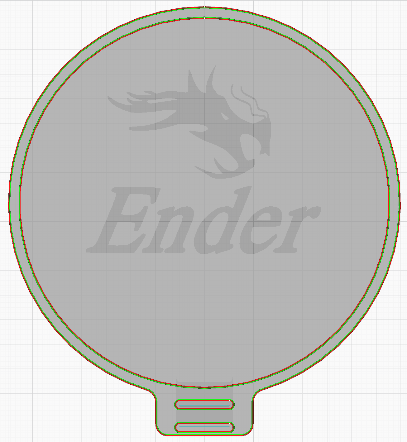 In this case I wanted to make the inner wall as stiff as possible, so I would prefer an infill that creates lines perpendicular to the inner wall (For the purpouse of this infill, the inner wall is the one closest to the part's center of mass). However I think there will be a lot of cases when someone wants to make the outer wall the stiffer, so it might be a good idea to offer the option of having either the inner of outer wall as the root of the radial line. Alternatively, a least material option in which each point of the the inner wall is connected to the closest point of the outer wall would eliminate any crossings of radial lines while offering somewhat of a midterm between inner and outer wall stiffness.
I believe that with these three settings most load cases will be covered if the radial wall stength is more important than than the layer adhesion strength. So the infill algorithm migh look a litte bit like this:
- Draw a concentric infill every C mm (which influences the Z strength and radial line overhang) and determine it's print area.
- Draw each radial line, based on the root wall setting and the infill percentage. This could be done somewhat like this:
2.1. Determine the desired radial lines area (DRLA) by multiplying the total infill area by infill percentage and then subtracting the concentric infill area; 2.2. Calculate an estimated radial line count (ERLC) by dividing the DRLA by the average of the inner and outer wall perimeters and the line width; 2.3. Draw radial lines from the root wall according to the selected radial line option. The perimetric distance between the starting points shall be the perimeter of the root wall devided by the ERLC.
2.4.1 Add the areas of the drawn radial lines and compare it to DRLA. Adjust ERLC and go to step 3 until the adjustment is oposite to a previous adjustment. 2.4.2. If the perimetric distance between the starting points on the root wall is less than the line width, maintain the drawn lines and start drawing lines on a new layer, that starts when the distance between adjacent lines is equal to the line width. You can define the start point location of the Nth line on the new layer as a point on a line averaging the Nth and N+1th lines of the first layer with a perpendicular distance between it and the first layer's Nth line equal to a line width, such as visualized in the following image:
2.4.3 Create new layers if there is no more space between the lines of the previous layer. If there is no more space in in the final layer, define the infill as 100% concentric.
Big +1 on the idea of doing something like this. One difficulty in devising a good algorithm for it is that the resulting infill path needs to be stable under perturbations in the wall paths, so that successive layers of infill have something underneath them to extrude against and bond to. If the paths change drastically from layer to layer, it will yield very poor part strength.
Due to a communication mixup, these issues have been left alone for far too long... sorry about that!
Please see the discussion in https://github.com/Ultimaker/Cura/issues/8811 so we can keep it all in one place.
For that reason, I have to close this one as a duplicate.